USD
CNY
中文
English
Russian
Hebrew
联系我们
热线:
0755-83212206
邮箱:
sale@pcgchips.com
联系我们
退款和退货
运输和交付
Cookies条款
条款和条件
隐私策略
集群科技
PCG-CHIPS.COM
登录
您好,欢迎访问
我的资料
订单状态和历史记录
询价历史
我的收藏
地址管理
登录
注册
×
所有产品
制造商
新闻
询价
关于我们
联系我们
技术支持
企业文化
账户中心
购物车
询价列表
USD
CNY
中文
English
Russian
Hebrew
所有产品
制造商
新闻
询价
关于我们
联系我们
技术支持
企业文化
登录
订单状态和历史记录
我的收藏
询价清单
比较
购物车
840329636
86-13510357183
sale@pcgchips.com
sale@pcgchips.com
https://www.instagram.com/
sale@pcgchips.com
live:.cid.c2ddceada28ad5f9
电阻器
电阻器
›
电阻网络、电阻阵列
配件
专用电阻
电感器、线圈、扼流圈
电感器、线圈、扼流圈
›
可调电感器
分立半导体产品
分立半导体产品
›
晶体管
RFQ
查看
物料清单工具
查看
制造商
查看
帮助您节省成本和时间。
为您的货物提供可靠的包装。
快速可靠的交付以节省时间。
优质的售后服务。
新品上市
更多 +
ULV 500 N 1 J
USD $169.25
ULV 1200 N 10 J
USD $217.83
ULH 200 50 J FL=1000
USD $97.17
ULV 500 N 20 J
USD $169.25
MPM20011002AT5
USD $6.97
MPM50011002DT1
USD $4.03
SOMC160110K0GRZ399
USD $3.75
MPMA10011002AT5
USD $7.37
ORNTA1001ZUF
USD $10.69
ORNTA5-1T0
USD $9
MPMA10015001AT5
USD $7.37
MDP1603100KGD04
USD $11.03
VSOR1601103JUF
USD $3.35
FGHL25T120RWD
USD $5.96
WSBR8536L0500JKB4
USD $38.39
WSBR8536L0500JKA4
USD $33.85
8BRN10K
USD $0.89
10BRN2.2K(4310R-101-222)
USD $0.89
10BRN10K(4310R-101-103)
USD $0.49
10BRN100K(4310R-101-104)
USD $0.79
10BRN4.7K(4310R-101-472)
USD $1.49
L101S471LF(4310R-101-471L
USD $1.65
RSL10X331G(4310R-101-331)
USD $1.95
F3L600R10N3S7FBPSA1
USD $209.52
F3L400R10N3S7FC1BPSA1
USD $195.03
SOMC16034K70GRZ
USD $3.47
SOMC160110K0GRZ
USD $3.47
MSP08A0110K0GDA
USD $6.01
HEIKIT1020050E29
USD $15.33
MDP16031K00GD04
USD $11.03
热卖零件
TDP16035002AUF
Vishay Dale Thin Film
USD $8.82
MPM10011002AT0
Vishay Dale Thin Film
USD $6.97
NOMC16031003FT5
Vishay Dale Thin Film
USD $4.33
MPMT1002AT5
Vishay Dale Thin Film
USD $6.2
TOMC16031000FT5
Vishay Dale Thin Film
USD $6.53
GTSM40N065D
Bruckewell
USD $28.23
CMSG120N013MDG
Bruckewell
USD $46.37
GTSM20N065
Bruckewell
USD $21.99
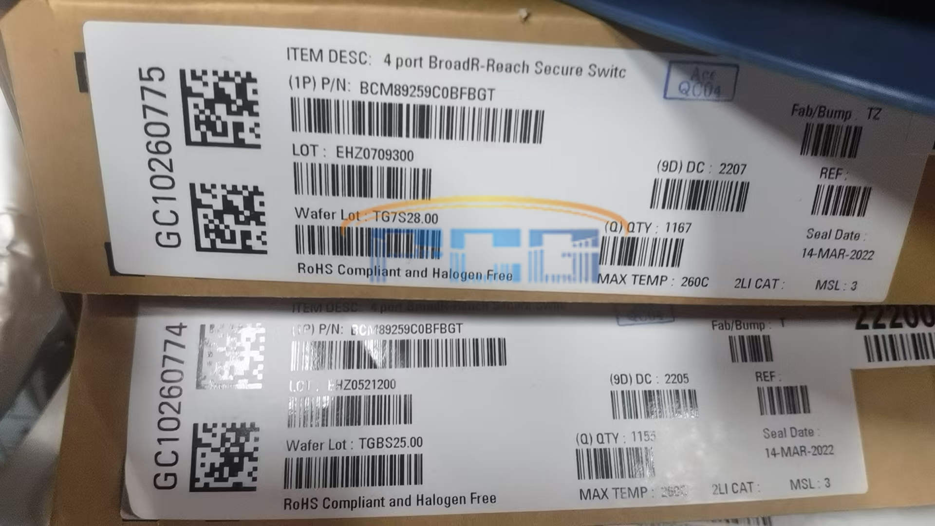
BCM89259C0BFBGT
USD $0
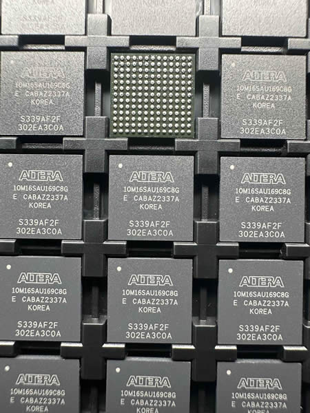
10M16SAU169C8G
USD $0
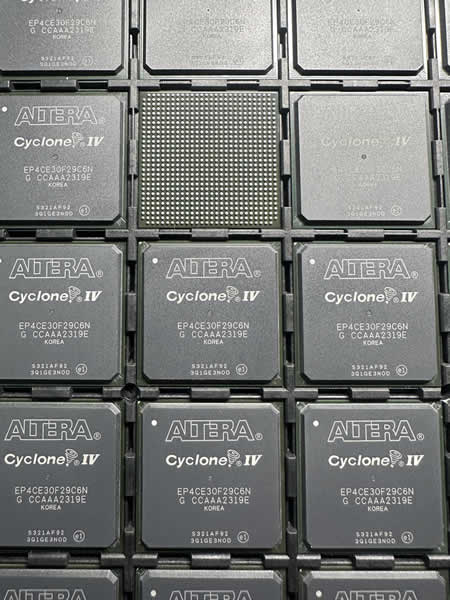
EP4CE30F29C6N
USD $0
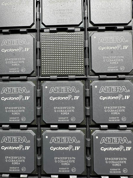
EP4CE55F23I7N
USD $0
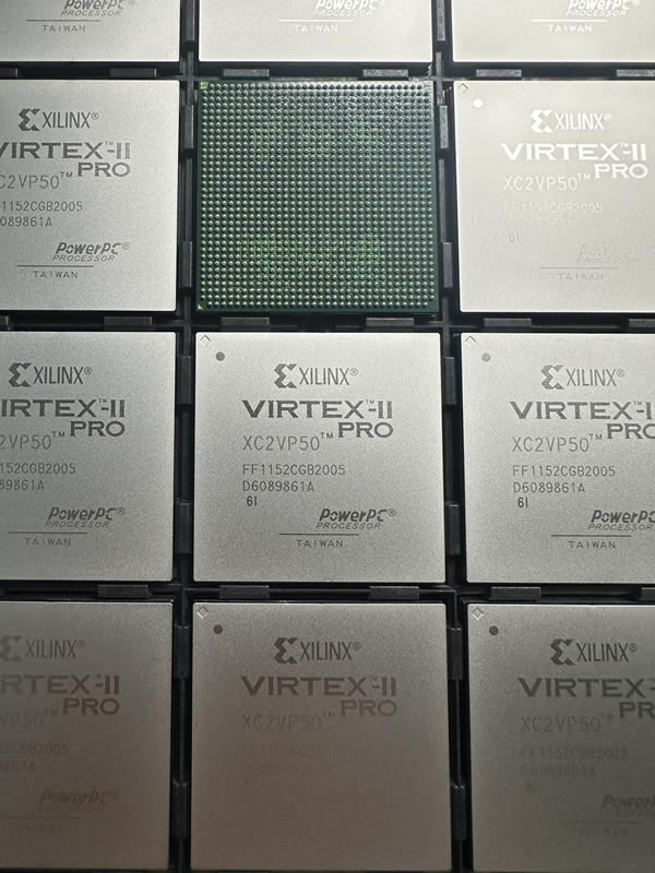
XC2VP50-6FFG1152I
USD $0
XC7K325T-2FFG676I
USD $0
XC7VX690T-1FFG1157I
USD $0
XCVU9P-2FLGA2104I
USD $0
XCZU15EG-2FFVB1156I
USD $0
ADSP-21060LCW-160
USD $0
4N35M
USD $0
6N136SD
USD $0
24LC64T-I/SN
USD $0
134D686X9100F6
USD $0
ABS25-32
USD $0
ACPL=M50L-000E
USD $0
ASD1282HIPWR
USD $0
B43504A9477M000
USD $0
BAT54C
USD $0
BLA9H0912L-1200P
USD $0
1757255
USD $0
1757255
USD $0
热卖
特惠
推荐
制造商
零件编号
价格
Vishay Dale Thin Film
TDP16035002AUF
USD $8.82
Vishay Dale Thin Film
MPM10011002AT0
USD $6.97
Vishay Dale Thin Film
NOMC16031003FT5
USD $4.33
Vishay Dale Thin Film
MPMT1002AT5
USD $6.2
Vishay Dale Thin Film
TOMC16031000FT5
USD $6.53
Bruckewell
GTSM40N065D
USD $28.23
Bruckewell
CMSG120N013MDG
USD $46.37
Bruckewell
GTSM20N065
USD $21.99
制造商
零件编号
价格
BCM89259C0BFBGT
USD $0
10M16SAU169C8G
USD $0
EP4CE30F29C6N
USD $0
EP4CE55F23I7N
USD $0
XC2VP50-6FFG1152I
USD $0
XC7K325T-2FFG676I
USD $0
XC7VX690T-1FFG1157I
USD $0
XCVU9P-2FLGA2104I
USD $0
制造商
零件编号
价格
Isabellenhuette USA
ULV 800 33 J FL=1000
USD $179.55
Isabellenhuette USA
ULV 300 N 150 J
USD $122.96
Isabellenhuette USA
ULV 1000 4 J
USD $186.26
Isabellenhuette USA
ULV 400 25 J
USD $130.68
Isabellenhuette USA
ULV 500 N 40 J
USD $169.25
Isabellenhuette USA
ULV 1000 100 J FL=1500
USD $193.14
Isabellenhuette USA
ULV 800 30 J FL=1000
USD $179.55
Isabellenhuette USA
ULV 200 75 J FL=1500
USD $99.05
制造商
零件编号
价格
Isabellenhuette USA
ULH 100 100 J FL=500
USD $70.74
Isabellenhuette USA
ULV 1000 30 J FL=1500
USD $193.14
Isabellenhuette USA
ULV 400 100 J FL=1500
USD $137.56
Isabellenhuette USA
ULV 500 N 60 J FL=500
USD $169.25
Isabellenhuette USA
ULV 400 75 J FL=1500
USD $137.56
Isabellenhuette USA
ULV 200 4 J
USD $92.17
Isabellenhuette USA
ULV 500 75 J FL=500
USD $154.57
Isabellenhuette USA
ULV 400 200 J FL=1500
USD $137.56
制造商
零件编号
价格
Isabellenhuette USA
ULV 500 N 1 J
USD $169.25
Isabellenhuette USA
ULV 1200 N 10 J
USD $217.83
Isabellenhuette USA
ULH 200 50 J FL=1000
USD $97.17
Isabellenhuette USA
ULV 500 N 20 J
USD $169.25
Vishay Dale Thin Film
MPM20011002AT5
USD $6.97
Vishay Dale Thin Film
MPM50011002DT1
USD $4.03
Vishay Dale
SOMC160110K0GRZ399
USD $3.75
Vishay Dale Thin Film
MPMA10011002AT5
USD $7.37
制造商
零件编号
价格
Vishay Dale Thin Film
ORNTA1001ZUF
USD $10.69
Vishay Dale Thin Film
ORNTA5-1T0
USD $9
Vishay Dale Thin Film
MPMA10015001AT5
USD $7.37
Vishay Dale
MDP1603100KGD04
USD $11.03
Vishay Dale Thin Film
VSOR1601103JUF
USD $3.35
onsemi
FGHL25T120RWD
USD $5.96
Vishay Dale
WSBR8536L0500JKB4
USD $38.39
Vishay Dale
WSBR8536L0500JKA4
USD $33.85
博客
微控制器STM32F030K6T6:一种高性能的嵌入式系统核心元器件
在当今的数字化时代,微控制器作为嵌入式系统的核心,扮演着举足轻重的角色。它们广泛应用于医疗设备、汽车电子、工业控制、消费类电子产品以及通信设备等多个领域。在这些微控制器中,STM32F030K6T6以其高性能、低功耗和丰富的外设接口等特点,成为了众多开发者心中的优选。本文将深入探讨STM32F030K6T6这一元器件的技术特点、应用领域及其在现代电子系统中的重要性。 STM32F030K6T6是由…
2025-05-08 16:35:16
PMIC-直流-直流开关调节器TPS54202DDCR技术特点解析
2025-05-08 16:35:19