SMA 50 Ohm Connector Specs: Latest Performance Report
Introduction: SMA 50 Ohm coaxial connectors remain a cornerstone of microwave interconnects for instrumentation and antennas due to their compact threaded design and predictable electrical behavior.
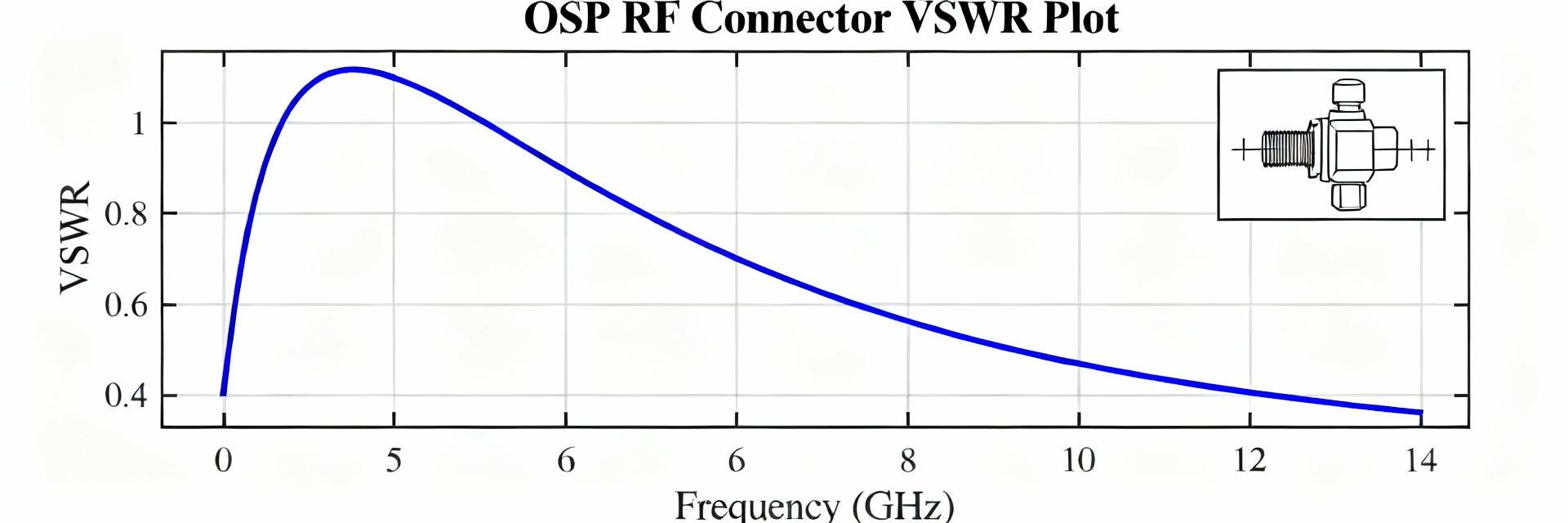
Evidence: Typical useful frequency coverage spans low megahertz up through the microwave band—commonly to 18 GHz and in precision variants out toward 26.5 GHz—with VSWR targets often in the 1.2–1.5 range.
Explanation: Those figures drive link-budget and measurement uncertainty, so knowing expected VSWR and insertion-loss trends is essential for test accuracy and system margins.
Frequency Range
VSWR Target
Insertion Loss
Background: Why SMA 50 Ohm Remains a Standard
Historical & Technical Rationale
The 50 ohm system impedance is a compromise optimized for power transfer and low loss in RF systems, and the SMA form factor delivers repeatable mating and small footprint. The threaded coupling minimizes axial play and provides consistent contact pressure; small center conductors and low-loss dielectrics keep parasitics modest up to microwave frequencies. For bench instruments, antennas and calibrated cable assemblies, the SMA 50 Ohm balance of electrical performance and mechanical practicality explains its longevity.
Typical Connector Variants and Use-Cases
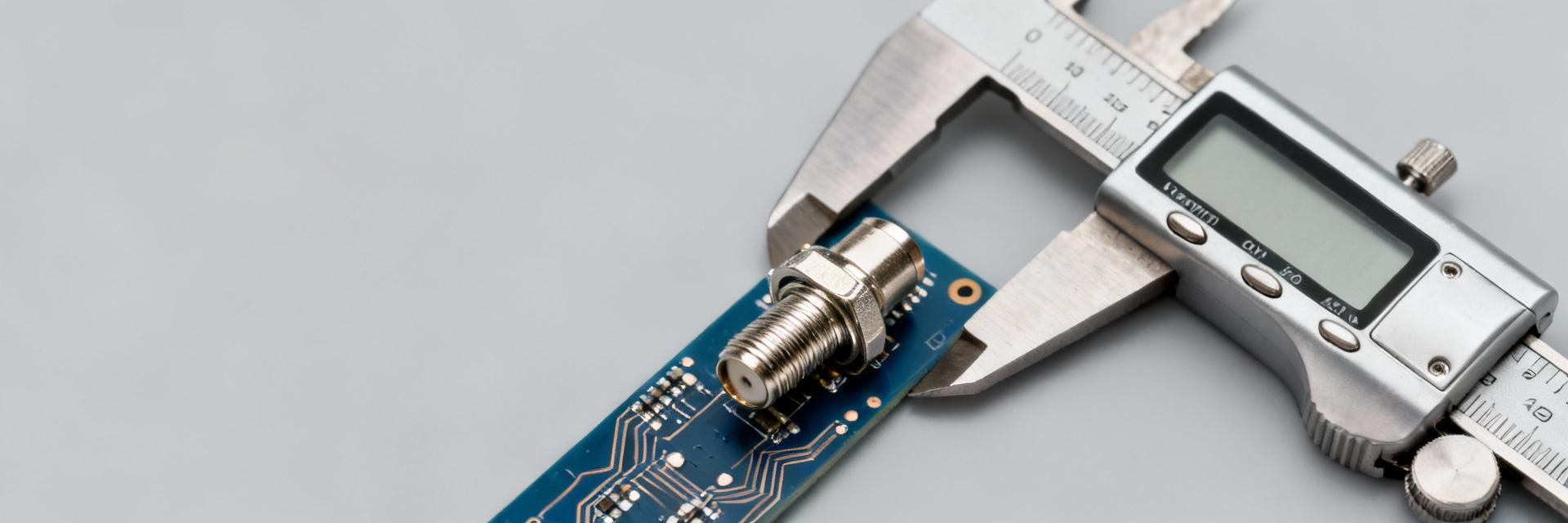
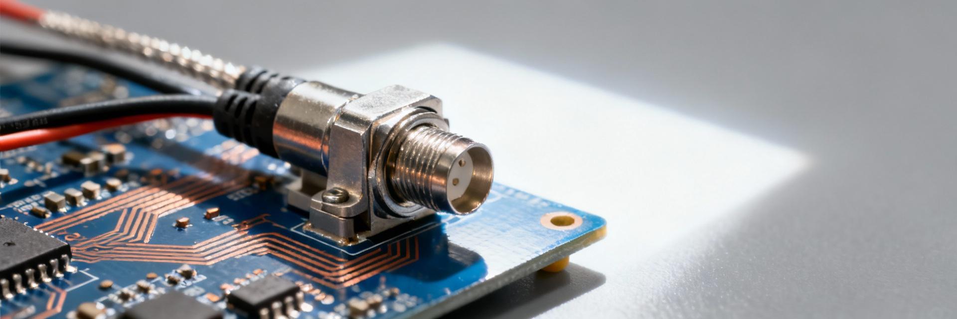
SMA variants include bulkhead jacks, PCB mounts, cable plugs and panel connectors, each targeted at different mechanical and RF trade-offs. Bulkhead and panel mounts prioritize mechanical robustness for field use; PCB and edge-mount jacks focus on compact board integration; cable assemblies emphasize repeatable impedance and low insertion loss. Engineers choose variants by required durability, mating cycles and maximum operating frequency—trading ruggedness for the tight tolerances needed at the highest frequencies.
Performance Benchmarks & Data Analysis
Key RF Metrics Benchmark
| Parameter | Standard SMA (18GHz) | Precision SMA (26.5GHz) | Typical Target |
|---|---|---|---|
| VSWR (max) | 1.35:1 | 1.20:1 | ≤ 1.25 |
| Insertion Loss (dB) | 0.15 √f(GHz) | 0.05 √f(GHz) | |
| Power Handling | ~150W @ 2GHz | ~100W @ 2GHz | Frequency Dependent |
Connector performance degrades predictably with rising frequency due to increased mismatch sensitivity and conductor/dielectric loss. Beyond ~12 GHz, small mechanical tolerances and dielectric inhomogeneities more strongly affect VSWR and insertion loss; precision designs extend usable range toward 26.5 GHz but require tighter manufacturing and inspection. Common failure modes include wear, contamination and incorrect torque—all of which increase reflection and loss.
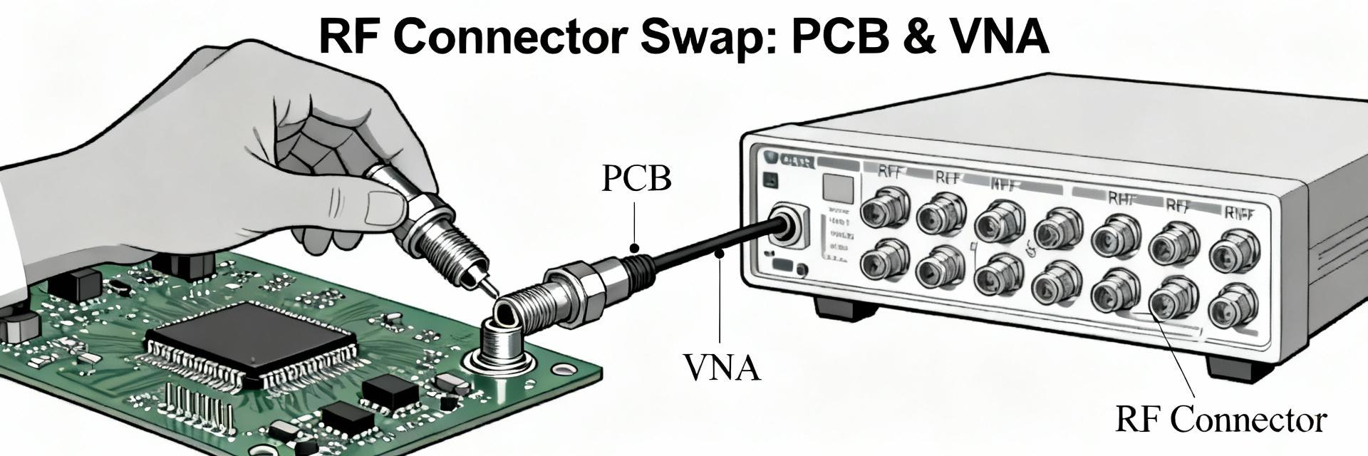
How to Test: Measurement Methods for Connector Specs
Recommended Test Setups
Accurate connector testing uses a calibrated vector network analyzer (VNA), well-characterized calibration standards, and controlled fixturing. A SOLT or TRL-style calibration to the intended measurement plane, low-reflection launchers, and stable cable assemblies minimize systematic error. Procedural steps—warm-up, calibration, defined torque application, and environmental control—produce repeatable sweeps.
Common Pitfalls & Corrections
Typical measurement errors stem from poor calibration planes and adapter reflections. Adapters introduce additional mismatch; de-embedding or direct-connect measurements reduce their influence. Always verify repeatability across multiple matings and use direct-connect where possible to reveal true connector specs.
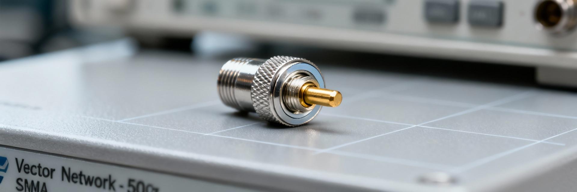
Connector Specs Deep-Dive: Materials & Mechanicals
- Conductive Plating: Gold over nickel for conductivity and corrosion resistance.
- Insulators: Low-loss PTFE or stable dielectrics.
- Mating Cycles: Typically rated for 500–1000 cycles.
- Contact Resistance: Usually
- Impedance Tolerance: 50 ± 1 Ohm (Precision variants tighter).
- Operating Temp: -65°C to +165°C typical range.
- Coupling Torque: 7-10 in-lbs (0.8-1.1 Nm) standard.
- Retention: ≥ 60 lbs axial force.
Field Case Study: Lab-to-Field Implementation
An instrument chain exhibited rising VSWR after field deployment. Root cause analysis found worn mating faces and under-torqued connectors contaminated by particulates. By cleaning, re-torquing to spec, and replacing worn connectors, the VSWR was restored to pre-deployment levels.
Installation Checklist:
Summary
- Why SMA 50 Ohm remains standard: Compact threaded design and balanced 50-ohm electrical characteristics make SMA 50 Ohm ideal for test benches and many microwave links.
- Key metrics to monitor: VSWR, insertion loss and isolation determine measurement fidelity—set acceptance bands by frequency and publish fixture-corrected data.
- Best practices and selection: Verify datasheet specs, use calibrated torque, and prefer precision variants for >18 GHz work.