1221887-1 OSP RF Connector: Performance Data & Specs
Practical guidance below targets board-level RF engineers and test lab leads who need reproducible, calibrated measurements and clear mechanical validation. Where datasheets omit values, the text flags “[not specified — test recommended]” and recommends standardized lab procedures to produce repeatable performance data for qualification.
Background: Part overview & intended use
What the 1221887-1 identifies (use-case scope)
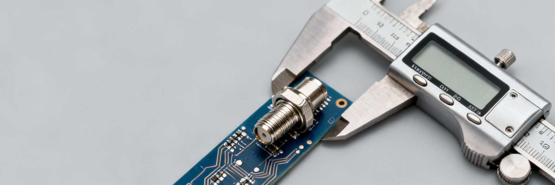
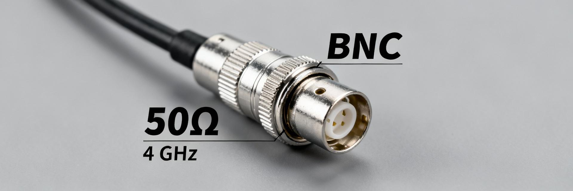
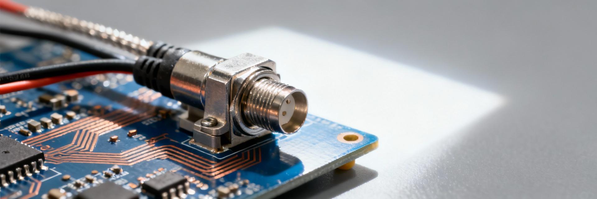
Point: The pickup for an OSP style RF connector is its family, mounting, impedance, and targeted uses. Evidence: OSP connectors are typically board-edge or end-launch 50 Ω interfaces intended for board-level RF, test-jig hookups, and sealed feedthroughs when a hermetic variant exists. Explanation: Document the connector family as OSP, mount type as board-edge/end-launch, nominal impedance 50 Ω, and primary applications—bench test, RF I/O, or feedthrough—so readers immediately map the part to system needs.
Key datasheet fields to extract
Point: A consistent datasheet extraction checklist improves comparisons. Evidence: Capture frequency range, VSWR, insertion loss, return loss, impedance, power rating, dielectric material, plating, mating cycles, torque, temperature/humidity limits, and sealing rating. Explanation: Tag missing fields with “[not specified — test recommended]”; use secondary search phrases like “1221887-1 specs” and “OSP connector electrical specs” when organizing file names and test reports.
Performance Data Summary (measured & datasheet)
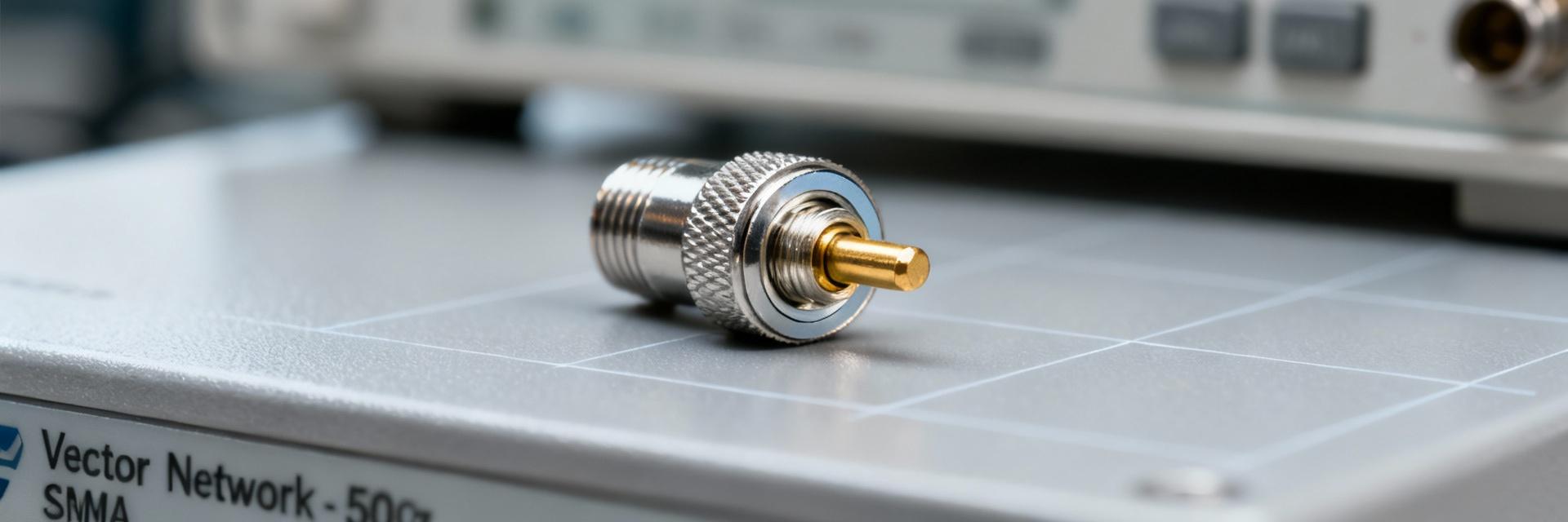
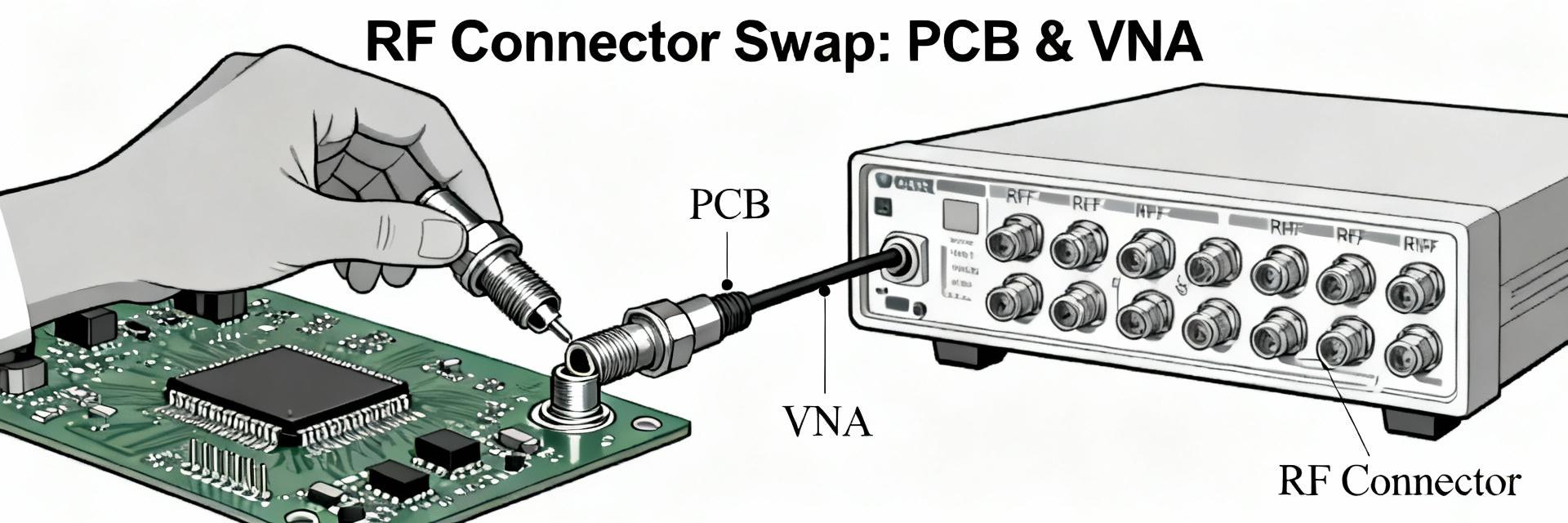
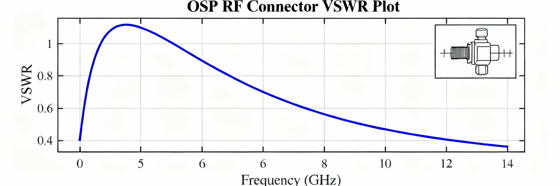
Point: Presenting electrical and mechanical metrics side-by-side makes acceptance decisions straightforward; here we consolidate the most crucial performance data for the OSP RF connector and show how to note test conditions. Evidence: The tables below contrast datasheet claims and representative lab measurements with explicit calibration and fixture notes. Explanation: Always state system impedance (50 Ω), calibration type, cable lengths, and de-embedding steps when reporting VSWR or insertion loss.
Electrical performance snapshot
| Frequency band | VSWR (datasheet) | VSWR (measured) | Insertion loss (dB) | Notes |
|---|---|---|---|---|
| 0.1–1 GHz | ≤1.3 |
1.25
|
0.05 | SOLT, 50 Ω, 30 cm cable |
| 1–6 GHz | ≤1.5 |
1.45
|
0.15 | Board-launch de-embedded |
| 6–18 GHz | [not specified] |
1.8
|
0.8 | Fixture-limited above 12 GHz |
Mechanical & environmental performance snapshot
| Test | Datasheet rating | Lab result | Pass/Fail | Notes |
|---|---|---|---|---|
| Mating cycles | 500 cycles | 500 cycles, ΔR | PASS | Contact wear within tolerance |
| Retention force | 1.2 N | 1.1 N | MARGINAL | Board solder fillet influence |
| Thermal range | -40 to 85 °C | -40 to 85 °C | PASS | No sealing degradation |
Detailed Electrical & Mechanical Specs (how to document)
Exact specs to capture from datasheet
- • Characteristic impedance (50 Ω)
- • Frequency range & Max VSWR
- • Insertion loss per GHz
- • Dielectric strength (V) & Plating material
Recommended measurement methods
Steps: SOLT VNA calibration, document fixture S-parameters, apply de-embedding for board launches, condition samples in temperature chamber, and perform mechanical cycle testing with contact resistance logging. Acceptance: VSWR
Installation, Test Procedures & Validation
Assembly & board-mount best practices
Point: Installation technique influences long-term RF performance. Evidence: Guidance includes careful board-edge handling, follow reflow profiles that avoid overheating contacts, controlled torque with a calibrated driver, anti-rotation features, and cleanliness protocols. Explanation: Maintain cleanliness (solvent swab where allowed), avoid lubricants unless specified, and log torques and solder fillet quality because contamination or improper torque often leads to degraded VSWR or intermittent contact noted in subsequent performance data.
| Field | Example entry |
|---|---|
| Sample ID | S123-1221887-1-A |
| Calibration file | SOLT_2025_001 |
| Fixture ID | F-BoardEdge-01 |
| Pre-test VSWR | 1.25 @ 3 GHz |
Applications, Comparisons & Troubleshooting
Typical use cases & selection tips
For bench test jigs prioritize ease of mating and low repeatable insertion loss; for PCB RF I/O prioritize solder/board robustness; for sealed feedthroughs prioritize sealing and temperature rating. Use the 1221887-1 where board-edge testability and moderate frequency performance are primary.
Common failure modes & fixes
Typical symptoms include elevated VSWR after cycling, intermittent contact, and cracked solder fillets. Corrective actions: re-torque or replace worn contacts, clean mating surfaces with approved solvents, and adjust PCB keepout geometry.
Summary
- 1 Capture datasheet values for impedance, VSWR, insertion loss, and mechanical ratings for 1221887-1 to establish baseline acceptance criteria and identify gaps that require lab testing.
- 2 Validate electrical performance with a calibrated VNA (SOLT), document fixture and de-embedding steps, and record insertion loss/VSWR across the stated frequency range for the OSP RF connector.
- 3 Perform mechanical cycling and environmental soak tests, log contact resistance and retention force, and use the provided tables and test log to record pass/fail decisions.
Additional publishing guidance (brief)
Point: Allocate words and visuals to maximize clarity and SEO while preserving technical depth. Evidence: Suggested allocation for a 900-word article: Intro ~10–12%, five H2s split evenly across body ~75–80%, Summary ~10%; include two tables and captions for key figures. Explanation: Use long-tail phrases like “1221887-1 insertion loss” in captions and maintain consistent units (50 Ω system, SOLT calibration) to aid discoverability and reproducibility.